
- Home
- News
How to Test Electrical Wires for Continuity?
Electrical continuity testing is a small measurement with serious consequences. A broken conductor can leave a lighting circuit dark, interrupt a control signal, or create intermittent equipment behavior. NFPA’s Home Fires Involving Electrical Distribution and Lighting Equipment report estimated 35,150 U.S. home fires annually from 2012 to 2016. These fires caused approximately 470 civilian deaths and $1.3 billion in property damage. The figures are dated, but the warning remains relevant.
This guide explains Testing Electrical Wires with a digital multimeter, continuity tester, or qualified diagnostic instrument. The process begins with isolation, not with touching probes. De-energize the circuit, verify the absence of voltage, and disconnect sensitive components before measuring. A beep can confirm a low-resistance path. It cannot prove that insulation is healthy, polarity is correct, or a connection will survive vibration. That limitation matters.
Look closely at the wire ends. Loose strands, darkened copper, crushed insulation, and green corrosion often reveal problems before testing does. Record the resistance reading, cable identification, and test conditions. Longer conductors naturally show higher resistance. Compare similar wires instead of judging one number alone. IEC 60364-based verification practices and NFPA 70B both emphasize documented inspection and maintenance for electrical systems. Still, standards cannot replace competent judgment. A continuity test may miss a fault that appears only under load. That is the uncomfortable part. Good testing reduces uncertainty; it does not eliminate it. When readings remain inconsistent, stop troubleshooting and involve a qualified electrician with suitable test equipment.
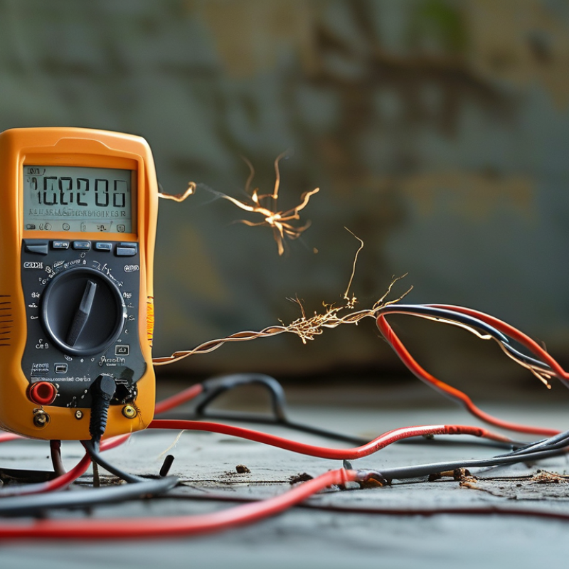
Define Wire Continuity Using IEC 60364-6 Test Requirements
How to Test Electrical Wires for Continuity?
Define Wire Continuity Using IEC 60364-6 Test Requirements
Wire continuity means an electrically complete path with sufficiently low resistance. IEC 60364-6 requires continuity verification for protective conductors and protective bonding conductors in low-voltage installations. The circuit must be isolated, locked against re-energization, and checked for absence of voltage before testing. Use a continuity or low-resistance tester that supplies at least 0.2 A, with an open-circuit voltage between 4 V and 24 V, as specified by the standard. Test from one end of each conductor to the other, then check protective bonding paths between exposed conductive parts and the main earthing terminal.
Record measured resistance, conductor identification, test current, and environmental conditions. A beep is not proof.
Resistance should remain stable when cables are gently flexed. Unstable readings may indicate a loose termination, damaged strand, or contaminated connection. IEC 60364-6 continuity testing does not confirm insulation resistance, polarity, or the conductor’s ability to carry design current. Those checks require separate procedures. This limitation is easy to overlook. The NFPA report Home Structure Fires Involving Electrical Distribution and Lighting Equipment estimated 26,100 U.S. home fires annually from 2015 to 2019, causing 280 civilian deaths and about 1,120 injuries. Reliable verification therefore depends on calibrated equipment, competent judgment, and complete records, not just a pass tone. A second test can expose mistakes.
Apply NFPA 70E Safety Steps: De-Energize, Isolate, and Verify
Testing electrical wires for continuity begins with NFPA 70E safety steps, not with the meter. De-energize the circuit at its disconnecting means. Apply a documented lockout/tagout procedure, and control every possible energy source. Isolate the conductors from connected equipment, parallel paths, capacitors, and control circuits. Then verify absence of voltage with a properly rated tester. Test the instrument on a known live source before checking the circuit, and test it again afterward. This three-point check matters because a failed tester can create false confidence.
Only after verification should continuity testing begin. Set the meter to continuity or resistance mode, then touch one probe to each end of the isolated conductor. A stable, low reading suggests an unbroken path; an open reading suggests a break, loose termination, or damaged conductor. Inspect the wire physically, especially near bends and terminals. Keep hands behind probe guards.
The U.S. Bureau of Labor Statistics recorded 145 fatal occupational injuries involving electricity in 2022, according to its Census of Fatal Occupational Injuries report. The number is a reminder that “off” is not proof of safety. NFPA 70E also emphasizes establishing an electrically safe work condition before work begins.
I have seen continuity readings change when a probe was poorly seated. That small error is easy to dismiss, and difficult to defend.
A continuity test confirms a path, not insulation quality, ampacity, or safe re-energization. Recheck assumptions.
Check Meter Function and Compensate for Test-Lead Resistance
How to Test Electrical Wires for Continuity?
Turn off power and isolate the wire before testing. Discharge nearby capacitors, then inspect the insulation and probe tips for damage. Set the meter to continuity or the lowest resistance range. Touch the probes together. The display should show a very low value, and the audible signal should respond immediately. If nothing happens, check the meter function, battery, and lead connections. Do not trust a silent meter until it passes this simple check. I once skipped this step and nearly blamed a sound wire for a weak battery.
Test-lead resistance can distort low-resistance readings. Keep the probe tips firmly together and note the displayed value. For example, if the meter reads 0.4 ohms, that value belongs to the leads and contacts. Use the meter’s zero or relative function if available. Otherwise, subtract 0.4 ohms from the wire measurement. A continuous wire should then read close to zero, although long, thin conductors may show slightly more resistance. Wiggle the wire gently during testing. A changing reading may reveal a broken strand or loose terminal. Repeat the test from both ends.
Test Each Conductor End-to-End Using a 200 mA Continuity Test
How to Test Electrical Wires for Continuity?
Test Each Conductor End-to-End Using a 200 mA Continuity Test
Before testing, switch off the circuit and verify that no voltage remains. Remove connected loads, lamps, and control devices from the conductor being checked. A connected component can create a false continuity path. Safety comes first.
Set the installation tester to its continuity function with a 200 mA test current. Zero the test leads if the instrument allows it. This step removes most lead resistance from the reading. Connect one probe to the conductor at the first end. Connect the second probe to the same conductor at the opposite end. The result should show a low, stable resistance. A clear tone may also confirm the path, but never trust sound alone.
Repeat the test for every conductor. Inspect both terminals while testing. A loose screw may produce an intermittent reading when the cable moves slightly. Wiggle the wire gently, not forcefully, and watch for resistance changes. Record each result, especially when several conductors look identical. A high or unstable value can indicate a broken core, poor termination, corrosion, or an unwanted connection.
Continuity is not insulation testing. A wire can pass this check and still leak current to another conductor. I have also learned that clean readings can hide a testing mistake, especially when both probes touch the wrong ends. Recheck conductor identification before accepting the result. Five extra seconds can prevent a costly assumption.
How to Test Electrical Wires for Continuity?
Expected end-to-end resistance of a 1.5 mm² copper conductor measured with a 200 mA continuity test current.
The values are calculated at approximately 20°C using copper resistivity of 0.0175 Ω·mm²/m: R = ρ × L ÷ A. At 200 mA, the corresponding voltage drop ranges from about 11.7 mV for a 5 m conductor to 233.3 mV for a 100 m conductor. A practical continuity result should be compared with the expected resistance, while allowing for connector and probe resistance.
Evaluate Resistance Readings Against Cable Length and Connection Quality
How to Test Electrical Wires for Continuity?
Turn off and isolate the circuit before testing. Confirm that no voltage remains with a suitable tester. Set the multimeter to resistance mode, then touch the probes together. The displayed value represents the test leads, so record or remove it using the meter’s zero function. A continuity beep is useful, but it does not explain the reading.
Cable length strongly affects resistance. A longer conductor has more resistance, while a thicker conductor usually has less. Material also matters. For a copper cable, estimate resistance from its length, cross-sectional area, and the conductor’s published resistivity. Test the complete path when possible. For example, a ten-meter circuit may include twenty meters of conductor in its return loop. Compare the measured value with the expected resistance, not simply with zero.
Connection quality can change the result. Clean probe tips, loose terminals, oxidation, or a weak crimp may create extra resistance. I once trusted a perfect continuity beep and missed a high-resistance joint. The cable passed, but the connection failed under load. Press the probes firmly and repeat the test. Gently flex the cable near plugs, junctions, and terminals. A stable reading is reassuring. An unstable reading needs investigation. Very high resistance suggests an open circuit, while a small but unexpected increase may indicate poor contact, excessive length, or a damaged conductor. Record the cable length and test conditions; otherwise, later comparisons become guesswork.
How to Test Electrical Wires for Continuity? - Evaluate Resistance Readings Against Cable Length and Connection Quality
| Cable Length (m) |
Copper Conductor Cross-Section (mm²) |
Theoretical Loop Resistance at 20°C (Ω) |
Clean Connection (+0.02 Ω) |
Acceptable Connection (+0.10 Ω) |
Suspect Connection (+0.50 Ω) |
Poor Connection (+2.00 Ω) |
Evaluation Guide |
|---|---|---|---|---|---|---|---|
| 10 | 0.5 | 0.69 | 0.71 | 0.79 | 1.19 | 2.69 | Longer or smaller wires naturally show higher resistance. |
| 10 | 1.0 | 0.34 | 0.36 | 0.44 | 0.84 | 2.34 | A low reading is expected for a short, larger conductor. |
| 10 | 2.5 | 0.14 | 0.16 | 0.24 | 0.64 | 2.14 | A small increase can be significant on a low-resistance circuit. |
| 25 | 0.75 | 1.15 | 1.17 | 1.25 | 1.65 | 3.15 | Compare the result with the calculated loop value, not with zero alone. |
| 25 | 1.5 | 0.57 | 0.59 | 0.67 | 1.07 | 2.57 | A stable reading near the calculated value indicates a sound path. |
| 50 | 1.0 | 1.72 | 1.74 | 1.82 | 2.22 | 3.72 | A reading around 1.7–1.8 Ω may be normal for this loop length. |
| 50 | 2.5 | 0.69 | 0.71 | 0.79 | 1.19 | 2.69 | A result above approximately 1.2 Ω suggests connection resistance in this example. |
| 100 | 1.5 | 2.30 | 2.32 | 2.40 | 2.80 | 4.30 | Long cable runs can pass continuity tests while still having measurable resistance. |
| 100 | 4.0 | 0.86 | 0.88 | 0.96 | 1.36 | 2.86 | A substantial rise above 0.86 Ω should prompt connector and termination checks. |
| Testing basis: Values are calculated for copper conductors at 20°C using a resistivity of approximately 0.01724 Ω·mm²/m. The theoretical loop resistance uses two conductors, so the electrical path is twice the one-way cable length. Connection columns add estimated total contact resistance of 0.02 Ω, 0.10 Ω, 0.50 Ω, or 2.00 Ω. Before testing, isolate the circuit, short the two conductors at the far end, measure the complete loop, and subtract the test-lead resistance. A continuity beep alone does not prove that a connection has low resistance. | |||||||
Related Posts
-
Exploring Different Examples of Testing Electrical Wires in Various Industries
-
5 Compelling Reasons to Choose the Best Testing Electrical Wires for Your Projects
-

China's Manufacturing Resilience: Succeeding Amidst US-China Tariff Challenges with Best Electrical Check
-

5 Essential Tips for Conducting the Best Electrical Appliance Checks
-

Comprehensive Guide to Electrical Safety Testing Standards 5 Must Know Insights for Global Buyers
-

Global Trust in Chinese Manufacturing Through Superior Visual Inspections on Electrical Equipment